|
|
|
Who's Online
There currently are 5905 guests online. |
|
Categories
|
|
Information
|
|
Featured Product
|
|
|
 |
|
|
There are currently no product reviews.
 ;
Great service. Fast response. High quality scan. Good price.
Thank you very much!!!
Oleg S.
;
Well-scanned, complete manual. Contains the information needed for repair and maintenance.
;
It's great to be able to obtain a precious technical information for a real old equipment. The one I got helps me a lot in the area of wiring diagram to repair my antique. PDF gave me clear enough information to find out thr details. Thanks for giving me the oppotunity to be able to access to almost vanished informations.
;
Another excellent aquisition. Fine detailed manual. Thanks
 ;
Good quality for the scan, complete, but as usual for Tascam, not so comprehensive !
INC
VAA12201-R.3581.A
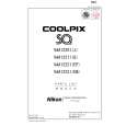
14. SB UNIT
â� Attach the SB flash unit ã�» Pass the red and white wires of the main condenser through the space between the pillar A and the wall of the joint unit. ï¼�ref. Fig.1ï¼� ã�» Put the yellow wire of the trigger around the outside of the pillar A, and assemble the flash unit. ï¼�ref. Fig.2ï¼� ã�» Attach 2 screws (#802). Noteï¼�In case of using a tweezer when arranging each wire (red, white and yellow) of the SB unit, be careful not to damage the cable sheath. ï¼�If using a sharp-edged tweezer, cover it with the constriction tube, etc. )
Pillar A of the joint unit
White �Red
Arrangement of red and white wires Fig.1
#802�2
Yellow
SB flash unit
Pillar A
Put the yellow wire around the outside of the pillar A Fig.2
�Attach the red and white wires of the main condenser to the both-sided adhesive tape that is attached on the lens-barrel. �ref. Fig.3� Both-sided adhesive tape
(#567)
�Note�Do not slacken the red and white wires, and do not allow them to put on the corner of the joint unit.
Corner of the joint unit Fig.3
- A17 ï½¥ SQ -
|
|
|
> |
|