|
|
|
Who's Online
There currently are 5865 guests online. |
|
Categories
|
|
Information
|
|
Featured Product
|
|
|
 |
|
|
There are currently no product reviews.
 ;
Great manual, great price. Has a few of the basic operating instructions that most service manuals leave out. Complete instructions for disassembling board by board, safety precautions, schematics, complete parts list.
;
I am very pleased with the service manual for my RT-909. This was an easy purchase and great procuct, and much cheaper than other venues i had looked at. This web site is now listed in my favorites list. KEEP UP THE GOOD WORK. THANKS. J. BROWN
;
A very well written and easy to understand manual.
;
There was no problem at all.After paying i had to wait only a few hours,than i could
download the manual in best pdf-quality.
Thank You !
 ;
I found this service manual to be complete in every detail except for troubleshooting charts. It would be helpful if it had a set of troubleshooting charts; however it is a very good manual otherwise and for the price it is very well worth it.
INC
VAA12201-R.3581.A
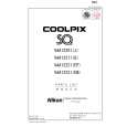
14. SB UNIT
â� Attach the SB flash unit ã�» Pass the red and white wires of the main condenser through the space between the pillar A and the wall of the joint unit. ï¼�ref. Fig.1ï¼� ã�» Put the yellow wire of the trigger around the outside of the pillar A, and assemble the flash unit. ï¼�ref. Fig.2ï¼� ã�» Attach 2 screws (#802). Noteï¼�In case of using a tweezer when arranging each wire (red, white and yellow) of the SB unit, be careful not to damage the cable sheath. ï¼�If using a sharp-edged tweezer, cover it with the constriction tube, etc. )
Pillar A of the joint unit
White �Red
Arrangement of red and white wires Fig.1
#802�2
Yellow
SB flash unit
Pillar A
Put the yellow wire around the outside of the pillar A Fig.2
�Attach the red and white wires of the main condenser to the both-sided adhesive tape that is attached on the lens-barrel. �ref. Fig.3� Both-sided adhesive tape
(#567)
�Note�Do not slacken the red and white wires, and do not allow them to put on the corner of the joint unit.
Corner of the joint unit Fig.3
- A17 ï½¥ SQ -
|
|
|
> |
|