|
|
|
Who's Online
There currently are 5372 guests online. |
|
Categories
|
|
Information
|
|
Featured Product
|
|
|
 |
|
|
There are currently no product reviews.
 ;
I'm very satisfied with your manual service. Your website made it easy to locate the correct manual. Also the quality is great and I never had a problem reading the fine details.
Thanks again.
Jeff Miller
JM Electronics
 ;
Good quality service manual German user manual. German user manual This is a quality scan of a manual in excellent condition and is just as good as having the original manual in hand
;
The manual for Sony LBT-D505 component stereo system is was excellent , with schematics, parts layout and parts list as well as instructions for adjustments for each component. Print was clear even when enlarged.
;
It's exactly a complete and very useful manual with all details what I needed. Thank you!I will come back whenever I need your manuals or schematics.
;
I searched EVERYWHERE looking for the manual/s on this "extinct" amp. Owner-Manuals.com made it available and for nearly nothing. Thanx to them, I can decipher the unknown cables and sort them out. Thanx, Owner-Manuals.com!!
INC
VAA12201-R.3581.A
14. SB UNIT
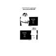
â� Attach the SB flash unit ã�» Pass the red and white wires of the main condenser through the space between the pillar A and the wall of the joint unit. ï¼�ref. Fig.1ï¼� ã�» Put the yellow wire of the trigger around the outside of the pillar A, and assemble the flash unit. ï¼�ref. Fig.2ï¼� ã�» Attach 2 screws (#802). Noteï¼�In case of using a tweezer when arranging each wire (red, white and yellow) of the SB unit, be careful not to damage the cable sheath. ï¼�If using a sharp-edged tweezer, cover it with the constriction tube, etc. )
Pillar A of the joint unit
White �Red
Arrangement of red and white wires Fig.1
#802�2
Yellow
SB flash unit
Pillar A
Put the yellow wire around the outside of the pillar A Fig.2
�Attach the red and white wires of the main condenser to the both-sided adhesive tape that is attached on the lens-barrel. �ref. Fig.3� Both-sided adhesive tape
(#567)
�Note�Do not slacken the red and white wires, and do not allow them to put on the corner of the joint unit.
Corner of the joint unit Fig.3
- A17 ï½¥ SQ -
|
|
|
> |
|